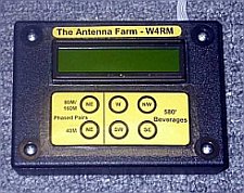
Remote
The four remotes each use a 16F628(a) PIC microcontoller. I tried to keep the code simple and generic, but each remote ended up using some unique time paramaters for initialization and different RS-232 communication flags. MBasic can only program the 16F628. So I used up the two non-A versions I had laying around and then used WinPIC to program the 16F628A. The code for both the A and non-A version is the same.

Buttons are arranged in a 3 X 2 matrix. The controller uses a scanning algorithm to detect which button was pressed. A logic 1 is placed on each row and the columns are sensed for a 1 or 0. If a 1 is detected, the program knows the corresponding button was pressed. The same PIC pins are used for the LCD display, so each row of the buttons is isolated with a diode.
LCD Module
MBasic makes it fairly easy to display the data. See the code for details. The LCD display is based on a Hitachi HD44780 controller, which is widely used and very common. The PIC code sends messages to the display as needed. There isn't anything special here other than I had to pay attention to the number of characters to make sure I didn't overwrite or underwrite to the LCD.
I used 2 line x 16 character LCD modules with a backlight. They came from Modtronix in Australia. I bought some hamfest specials without backlights and they weren't as nice looking.
RS-232 Communications
Four pins are used for the RS-232 signalling; RX, TX, RTS and CTS. The RX and TX lines for the remote are tied in parallel and they connect to the TX/RX lines of the master. The remote is wired as a DTE and the master is wired as a DCE. The TX/RX lines are crossed. Both units use a MAX-233A (no caps) for RS-232/TTL conversion. Of course, these converters also invert the logic.
The TX lines are tied to the master's RX line through a diode. (One for each remote.) This provides a wired-or function and ensures each remote can safely drive the master's RX line.
The CTS and RTS lines for all the remotes are connected together in a diode matrix to provide hardware handshaking. The RTS send line for each remote is connected to the CTS line of the other three remotes. The RTS and CTS lines are NOT connected to the master controller. So the remotes 'fight it out' for the RS-232 bus. Since the remote ALWAYS initiates the message exchange, this works fine.
When a button is pressed, the PIC checks the CTS line. If the line is low, the RS-232 bus is free. (The code looks for a 1 because the MAX-233's invert the signal.) The remote sends a message to the controller, which consists of the station number and antenna request. The message consists of a single byte with the station number in the 4 most significant bits and the antenna number in least 4 significant bits.
The master parses the message and selects the corresponding antenna. The return message consists of a S#, where # is the station # and the message to be displayed on the remote. The remote waits for the S# message and then reads in the next 16 bytes. The message is displayed on the LCD. If a message isn't returned within 2 seconds, the remote displays a 'Time Out' error message.
I had to use the S# protocol because the master's PIC TX line is tied to all remote RX lines. So all the remotes sense ALL the TX data from the master. The S# protocol allows the remote to select it's own messages. (This was kind of tricky.)
During start up - each remote sends an 'init' message to the master using the same handshaking technique. If the init message is recieved, a new RX Antenna Select message is displayed on the remote. No antennas for the radio are selected until the first button is pressed.
Buttons 1 - 6 select the cooresponding antenna. If both 5 and 6 are pressed at the same time, all antennas are deselected (released)
Construction
The board were wired with point to point wiring. Two remotes used 10MHz resonators and two used 20MHz. They were different because I wanted to use up the 10MHz resonators I had in the shack. The 1M resistor is required! The boards were glued into the plastic cases using 'Gorilla' glue, which expanded during curing. So I had to make sure they were weighted down.
I drilled six holes for the push button switches and mounted the switches on perf board under the holes. The tops of the switches protruded slightly above the plastic case. Then, I printed a label on yellow copy paper and used packing tape to attach the label over the switches. This made a great 'membrane,' which hid the ugly holes below.